Introduction
Modulation by frequency shift (FSK, Frequency Shift Keying) is a digital modulation technique where binary information is transmitted by varying the frequency of a carrier between two or more discrete values. In its simplest form, 2-FSK, a bit 0 is represented with a specific frequency (f0) and a bit 1 with another (f1). This technique is widely used in low-speed wireless communications, such as remote controls, telemetry systems, RFID, and IoT devices.
To analyze and interpret this type of signals, a very useful tool is Universal Radio Hacker (URH). URH allows capturing, visualizing, and decoding digital radio transmissions in an interactive way. Through its graphical interface, it is possible to observe how the frequencies that represent the bits alternate and, with a manual analysis process, deduce the structure of the transmitted messages. The manual decoding in URH implies:
- Capture of the signal through an SDR compatible device.
- Visualization in the temporal and frequency domain, where the jumps between the two frequencies of FSK modulation can be identified.
- Segmentation and conversion of symbols, transforming frequency changes into a sequence of bits.
- Pattern analysis, which allows discovering frames, preambles, checksums and possible protocols used.
This procedure provides not only the possibility of “reading” what is transmitted by a device, but also understanding the internal structure of its communication, which proves to be valuable in tasks such as reverse engineering, cybersecurity and radio frequency experimentation. As a transmitter, we will use a Flipper Zero device with pre-generated signal.
Analysis of the spectrum and signal capture
Firstly, we will search for different frequencies in the radioelectric spectrum by the emitted signal. We will use the Spectrum Analyzer function accessible from the File menu of URH. We will configure the device RTL-SDR on a frequency of 433,920 MHz, with a bandwidth of 1 MHz. We will adjust the gain according to the received signal power and since FSK is the signal, we will disable the Apply DC correction option.
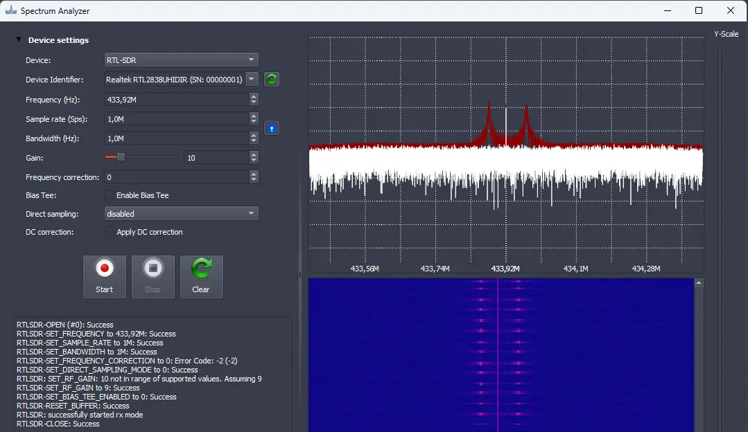 We observe clearly a 2-FSK signal, with two clearly differentiated frequencies (433,876 MHz and 433,971 MHz) along the carrier (433,920 MHz). With these data, we calculate the deviation of
 f0 and f1 from the carrier signal of around 48 KHz, coinciding with one of the modulations included in the Flipper Zero, 2FSK_476. We can proceed to record the signal and analyze it with the option Record Signal.
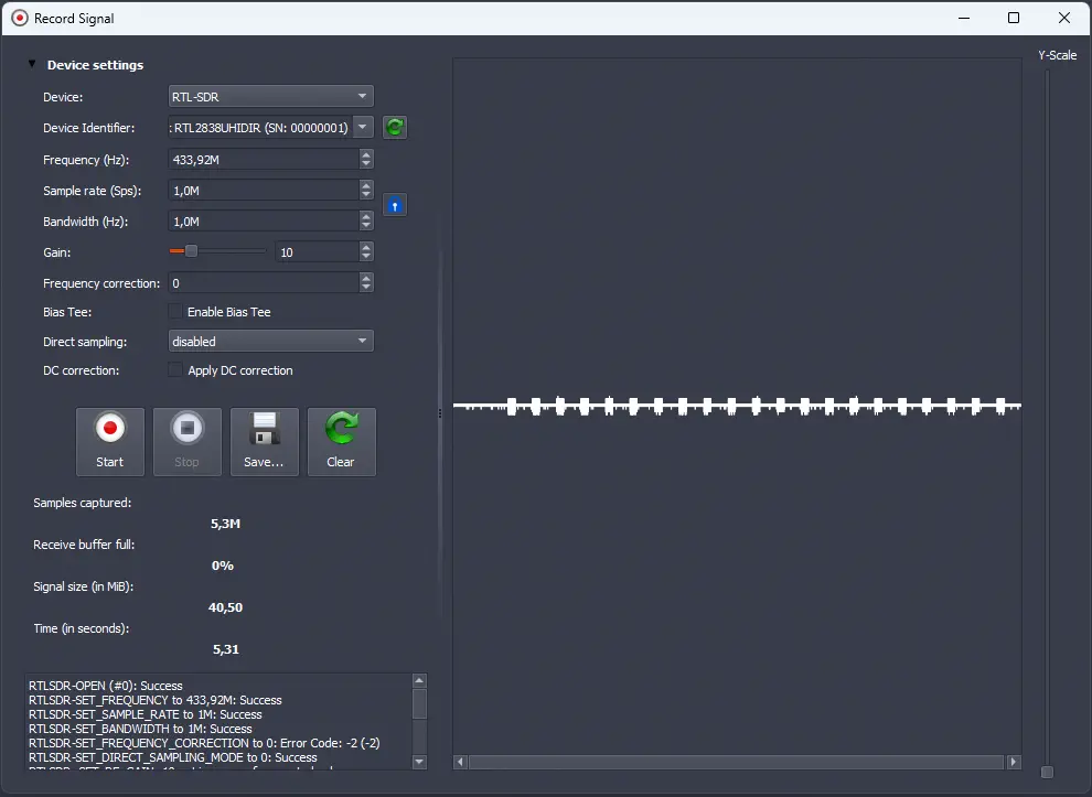 We save the signal with
 Save and when we close the window, it will load the signal in the program.
Analysis of the signal
Firstly, we will use the Y-Scale selector to change the scale of the y-axis of the signal, in order to observe the signals more visually. Next, we will perform a filtering of the signal if the received signal is of low power using the Filter (moving average) button.
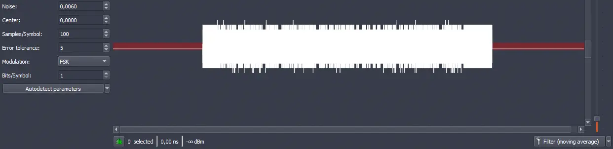
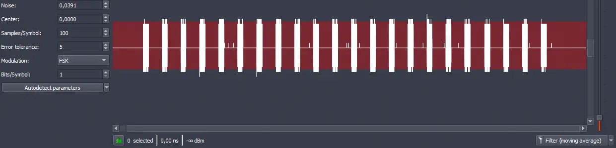 Now we need to filter out the noise from the signal. Each of the segments that appear in the signal is one of the received signals, and the remaining part of the signal is noise. We will select the noise by changing the value of the option
 Noise. The area of the noise will be marked in red. In this case, the signal is quite clean due to filtering. We obtain a Noise value of 0.0060.
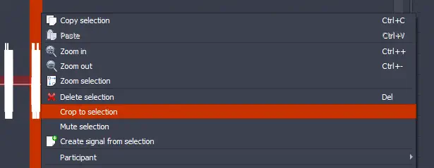
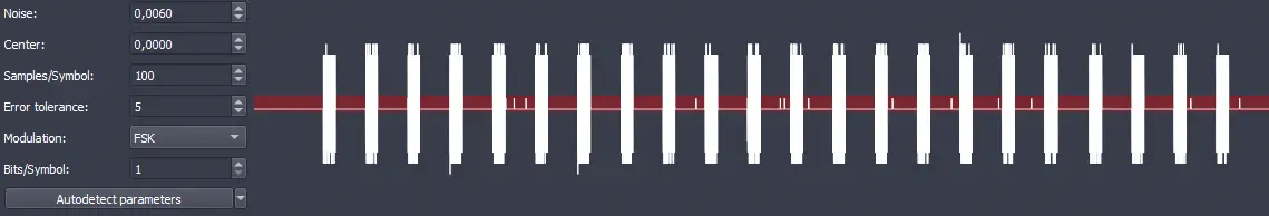 We observe that the different signals are similar so we will focus on one of them, select it, right-click on the signal and cut it with the option
 Crop to selection.
 This is the resulting signal:
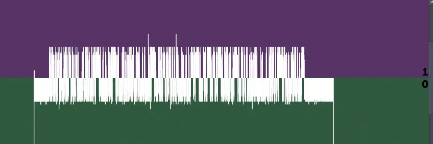
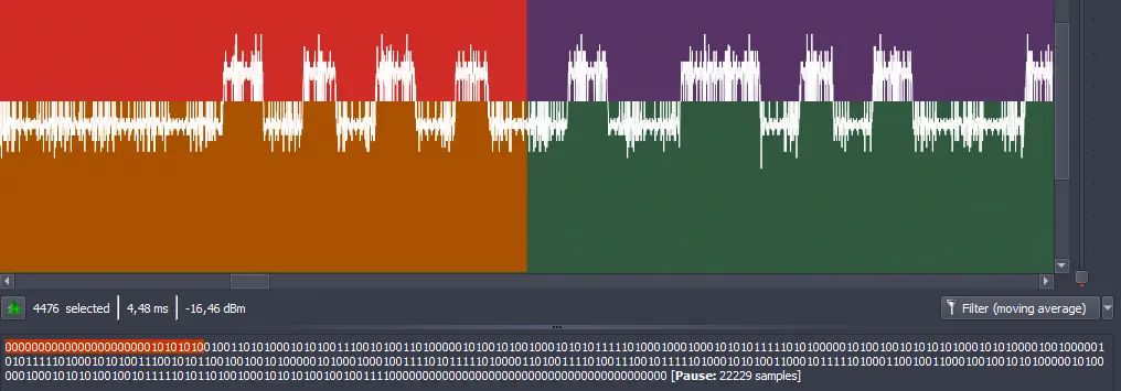
 Next we can demodulate the signal by selecting the option
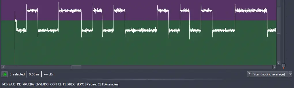
 Demodulated in Signal view. The demodulated signal will be shown, so we need to use the option Y-Scale to adapt the signal to the screen. Two areas have been created on the screen, red and green. If the signal is in the red area, a binary state of 0 will be determined. If the signal is in the green area, a binary state of 1 will be determined.
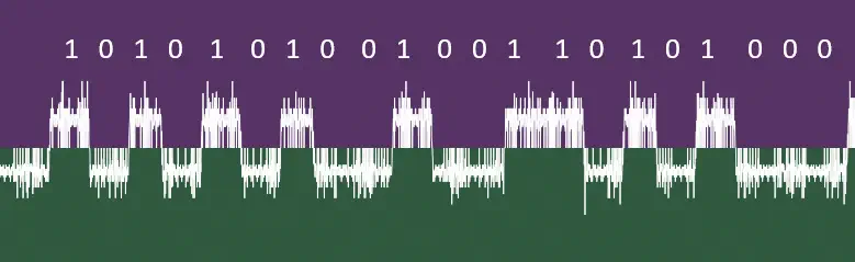
 Then we will make a zoom on the signal to observe it bit by bit. We observe a signal in the shape of a “spike”, although it is clearly visible that the state is either
 0 or 1. This would be a visual decoding:
 This signal format is due to the weak power received. It may be possible to recapture the signal by increasing gain, later, since with this signal the correct decoding can be made. We must find the duration of the bit to update the
 Samples/Symbol value. To do this, we will select for example the value 1 in the demodulated signal and observe the lower text.
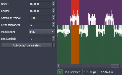 The bit has a duration of 151 us or 151 samples because the captured signal has a bandwidth of 1 MHz. So we update the value. The next error tolerance
 Error tolerance will depend on the quality of the captured signal. If the quality of the signal is good without the “spike” format, we can use the value 0. In this case with the value 0, we observe that the signal is not being decoded, so we change to the value 1 because it visually appears to be correctly decoding observing the lower binary code.
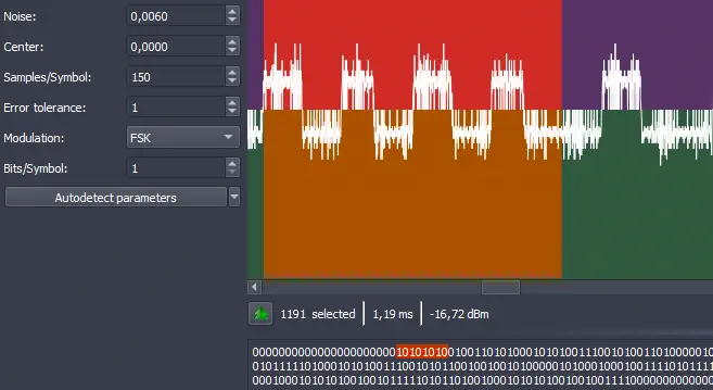 As modulation we set the value
 FSK and in this case the option of Bits/Symbol that indicates how many bits each symbol takes and changes according to the modulation is set to 1, in the case of the 2-FSK modulation. We can now observe the decoded signal.
 At the start of the signal we observe several values at
 0. Next we observe a pattern 10101010. This usually corresponds to a preamble, a series of bits used for synchronizing the receiver with the transmitted signal by the transmitter (as we have used it before to calculate the duration of the bit signal). We can select these bits and remove them since they do not contain any data.
 We can convert the decoded signal to an ASCII string by selecting
 ASCII in Show data as.
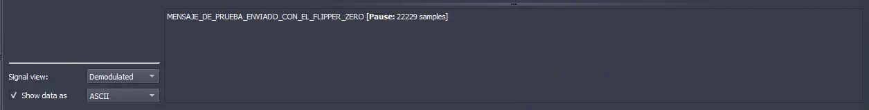 We obtain the message
 MESSAGE_SENT_WITH_THE_FLIPPER_ZERO. We re-capture the signal with a higher gain and observe a cleaner signal.
 The signal emitted by the Flipper Zero has been generated with the tool SubGhz Generator using the following command:
$ python flipper_subghz.py raw --freq 433920000 --preset 2FSK_476 --text MENSAJE_DE_PRUEBA_ENVIADO_CON_EL_FLIPPER_ZERO --te 150 --preamble 10101010 out.sub
Wrote RAW .sub to out.sub
Conclusion
Manual decoding of FSK signals with Universal Radio Hacker allows understanding in detail how a device transmits digital information through radio frequency. From an example, it is possible to observe how the bits are represented by two distinct frequencies, transforming them into a binary sequence and discovering the structure of the transmitted frames.