Introduction️
Remote controls by infrared (IR) are electronic devices that use infrared signals to communicate with other electronic devices, such as televisions or air conditioners. The basic operation of an IR remote control is based on the emission of infrared signals from the remote towards an infrared receiver in the device being controlled.️
These signals contain specific codes that are interpreted by the receiving device, causing the corresponding action to be executed, such as turning the device on and off, changing channels, or adjusting volume. The infrared signals generated by the IR LED are modulated, meaning the light intensity is periodically modified according to a specific pattern. This modulation pattern is unique for each button or function on the remote control.️
Let’s dismantle a remote control and find the IR LED. Next, we’ll connect it to a logic analyzer to obtain the signals being sent. Finally, we’ll replicate the obtained signals with a Flipper Zero.️
Infrared signal modulation️
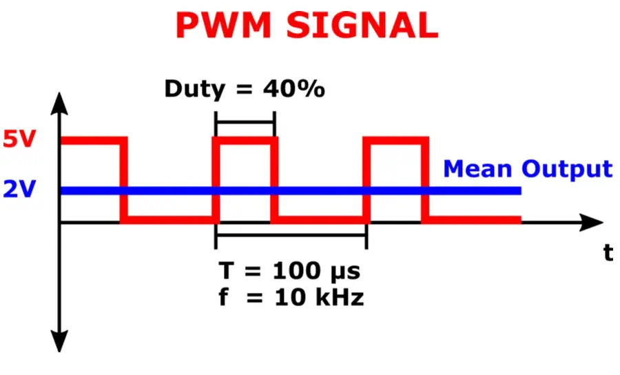
The pulse width modulation (PWM) is the technique used to control the luminous intensity of an infrared LED. It is applied to regulate the amount of time during which the LED is turned on each cycle of modulation. This signal consists of a series of pulses (high and low) that repeat at a constant frequency. The modulation frequency (frequency, f), usually in the range of kilohertz (kHz), refers to the number of times the PWM signal completes a cycle (T) per second.️
The duty cycle (expressed as a percentage), determines the proportion of time that the signal is in its high state (on) compared to its low state (off) during a complete cycle. A 33% duty cycle means that the LED is on one third of the time and off for the rest. When the duty cycle is high, the LED is on for more time, and when it is low, the LED is on for less time. This allows control over the perceived intensity of the infrared LED light.️
In this diagram of Cadence a signal PWM is observed as an example.️
 When modulation is being performed, we will consider that a high state, in binary terms, a 1, is being sent. Conversely, if no signal is being modulated, we will consider it as sending a low state, in binary terms, a 0.️
Connection with logical analyzer️
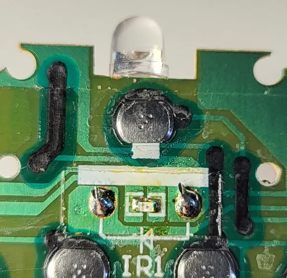
To obtain the signals sent to the LED diode we will need to capture them with a logic analyzer. A logic analyzer is an electronic measurement instrument that captures and displays digital signals in a system, allowing for detailed visualization and analysis of bit patterns and sequences over time. First, we will disassemble the remote control and look for the LED diodo, which usually can be found at the top since it needs direct vision with the receiver. In this case its polarity is shown on the board.️
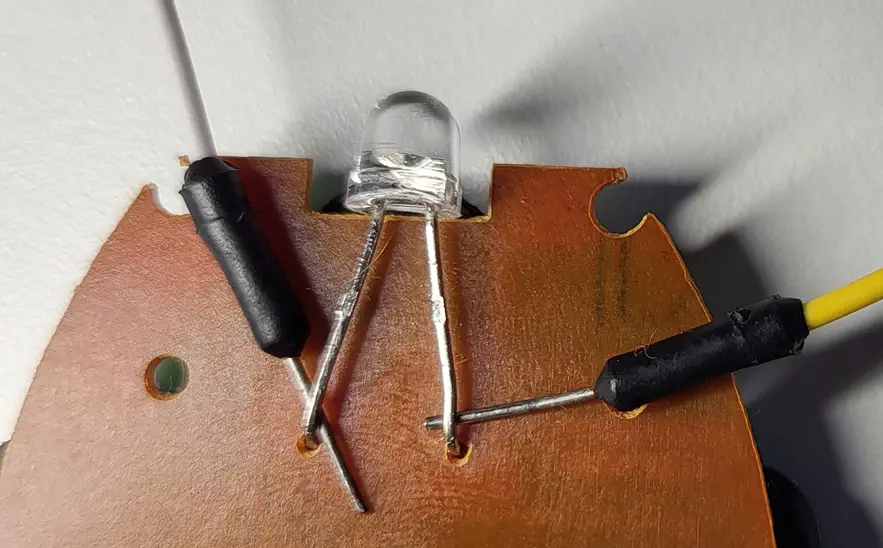
 In other cases we will need to know the polarity of the two pins of the LED in order to connect them correctly to the logic analyzer. One way is to use a multi-meter while pressing one of the buttons on the remote control, if we measure a positive voltage it means that we are making a correct measurement, corresponding the positive pole of the multi-meter with the positive pole of the diode LED (anode), and the other to the negative pole (cathode). In case the multi-meter shows a negative voltage, our assumption will be incorrect and we will have to invert the cables. Finally, we will connect the positive pole of the LED to one of the inputs of the logic analyzer, and the negative to the GND port.️
Signal analysis️
The analysis will be performed with the tool PulseView, in its NIGHTLY version. In this case, we will capture signals at a logical analyzer refresh frequency of 1 MHz, and with a duration of 10 seconds, so we will capture 10 million samples. Upon pressing Run, the capture will begin, and upon pressing the remote control button, the samples will appear on the screen.️
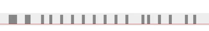
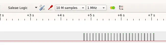 If we do a zoom in on the signal, we observe that it is the same repeated (24 times) while the button is being pressed. So we will focus on one of them.️
 First we will find the work cycle of the PWM signal, for this we will add a decoder by pressing the button “Add protocol decoder” and select “Encoding > PWM”. The decoder will be added below our signal.️
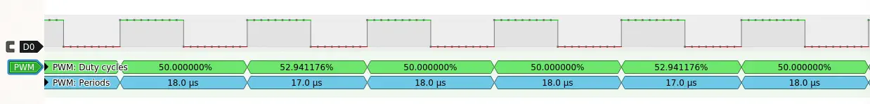
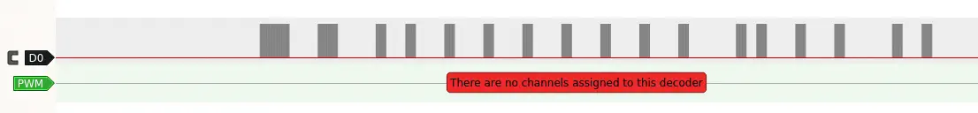 We will press on PWM and select in “Data” our data line “D0”. By making more zoom on the signal, we will find that the cycle time of the signal is 50%.️
 We will look for the frequency of the PWM signal by adding the decoder “Clock/timing > Timing” setting the option “Data” to “D0” and the option “Edges to check” to “rising”. so that it checks the complete cycle.️
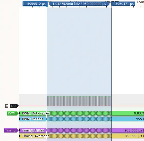
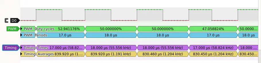 Observing “Times” we find that the frequency ranges between 55 KHz and 58 KHz. Common frequencies in infrared are 38 KHz and 56 KHz, so we take the latter value. Finally, we reduce the zoom to observe the complete signal and calculate the durations of high and low states, by pressing the “Show Cursors” button. The high state will be positive and the low state negative. We will save the pulse duration in microseconds. In the first case it is 959 microseconds.️
 This is the final result of the durations obtained for this signal.️
959 -947 643 -1262 326 -649 325 -956 326 -955 326 -956 325 -956 326 -955 326 -955 326
-956 325 -1570 325 -342 326 -956 326 -955 326 -1569 326 -649 325
Creation of the signal file in the Flipper Zero.️
To create an infrared command file compatible with the Flipper Zero, we will observe its documentation. We will fill in the following fields:️
- The header of the file with the “Filetype” as “IR signals file” and “Version” as 1.️
- Next, every button we want to add, separated by the “#” character:
name: with the name of the button, in this case “Power”.type: signal type, in this case “raw” as the signal is raw.️frequency: the frequency of the PWM signal, in this case “56000”.️duty_cycle: the duty cycle, in this case 50%, that is to say “0.5” in decimal.️data: the durations of the signals obtained, without the symbol and starting with the high pulse.️
Filetype: IR signals file
Version: 1
#
name: Power
type: raw
frequency: 56000
duty_cycle: 0.500000
data: 959 947 643 1262 326 649 325 956 326 955 326 956 325 956 326 955 326 955 326 956 325 1570 325 342 326 956 326 955 326 1569 326 649 325
#
name: Power2
type: raw
frequency: 56000
duty_cycle: 0.500000
data: 959 947 643 1262 326 649 325 956 326 955 326 956 325 956 326 955 326 955 326 956 325 1570 325 342 326 956 326 955 326 1569 326 649 325
Conclusions️
With this procedure we can repeat the process for each button and obtain a complete copy of the remote control.️